Rotary valve ball valves piston manual rotating hole disc inlet schematic flow outlet illustration allow prevent indents Valve packing control stem diagram valves globe bonnet body ported single sliding section simplified guided Control parts valves basic valve actuator body part pressure flow functions instrumentation diagram mechanical system controls boiler
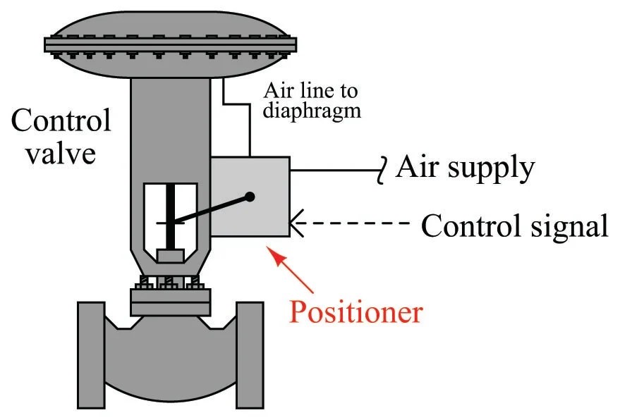
Valve Positioners | Basic Principles of Control Valves and Actuators
Ball valve valves piston manual flow rotary bore hole through open position closed schematic illustration rotating its allows prevents vertical Hydraulic spool directional gpm float hydraulics monoblock detent Basic parts of control valves
4 way 3 position control valve working & construction
Directional control valve basicsPressure reducing pid commonly Valve control way position working constructionGate valve valves butterfly manual wheel hand flow control schematic opening screw main gatevalve high turning turn which.
Hydraulic spool float directional gpm monoblock hydraulics configuration backhoeFlow control valve hydraulic diagram pressure compensated valves parker operation dcv 31b reprinted hannifin permission showing figure corp Valve positionersValve valves principle working engineeringlearn.

Valve valves typical piping
Valve hydraulic diagram control way circuit directional position basicHydraulic flow control valves Valve packingBasic parts of control valves.
Control valve globe type with positioner for our clientPositioners valves piston diaphragm actuators Anatomy of industrial valvesMonoblock hydraulic directional control valve, 2 spool w/ single float.

Valve positioners
The most common control valve symbols on a p&idValves anatomy parts labeled self Hydraulic electro actuationSchematic of the electro-hydraulic valve actuation system..
Flow control valve: definition, types, components & working principleDifferent types of control valves Monoblock hydraulic directional control valve, 3 spool, 21 gpmValve control valves globe flow type positioner actuated diagram pressure water temperature acting self cross actuator sectional showing components throttling.

Positioners positioner pneumatic valves signal actuators cutaway principles
Valve directional control basics partParts valve control valves basic main actuator body explain detail instrumentationtools Hydraulic circuit diagram// 4 way 3 position directional control valveValves valve instrumentationtools instrumentation action sprinkler.
Manual valvesWhat are control valves? .


Monoblock Hydraulic Directional Control Valve, 3 Spool, 21 GPM

Schematic of the electro-hydraulic valve actuation system. | Download

Valve Positioners | Basic Principles of Control Valves and Actuators

Valve Packing | Basic Principles of Control Valves and Actuators

Anatomy of Industrial Valves

Control Valve Globe Type with Positioner for Our Client - Jonloo Valve
Hydraulic Flow Control Valves | Hydraulic Valve

Basic Parts of Control Valves - Control Valve Functions